Introduction
This document - and an associated video presentation - describes the architecture of EdgeVPN.io, at a high level - not diving deep into the code, but overviewing the major modules and their interactions. The target audience is developers who are interested in contributing to the code base.
Background
EdgeVPN.io is the evolution of IP-over-P2P (IPOP) codebase. IPOP has gone through significant architecture and implementation changes over time - for reference, an overview of these changes appears in the 2020 IEICE paper This architecture overview reflects the 4th generation of the architecture, which is the basis for the software.
Overview and terminology
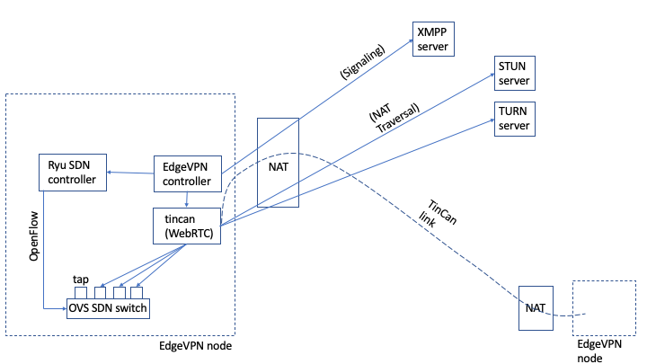
EdgeVPN.io integrates several technologies and standards to deliver a flexible virtual network. These include NAT traversal, signaling, tunneling, network virtualization, overlay networking, and software-defined networking. To get started, the following diagram provides an overview of how various modules come together, and basic terminology used throughout this document:
-
NAT: A Network Address Translator
-
EdgeVPN.io node: a (virtual) machine that runs the software. A full deployment consists of a set of nodes, whereas nodes may have private addresses and subject to NAT(s).
-
XMPP server: a (virtual) machine that runs a server compliant to the XMPP messaging protocol. Typically, a deployment uses a single XMPP server with a public Internet address
-
STUN server: a (virtual) machine that runs a server compliant to the STUN protocol. A deployment requires at least one STUN server (possibly more, for fault-tolerance) with a public Internet address
-
TURN server: a (virtual) machine that runs a server compliant to the TURN protocol. A deployment may use one or more TURN servers (for fault tolerance and load balancing) with a public Internet address
-
WebRTC: an open framework for the web that enables Real-Time Communications (RTC) capabilities. WebRTC is implemented in C++
-
TinCan link: an abstraction of a virtual link that carries encapsulated, encrypted Ethernet frames between two nodes. A TinCan link builds upon a WebRTC connection; the tincan process implements this abstraction. The tincan code is implemented in C++
-
SDN: Software-Defined Networking. The SDN architecture decouples the network control and forwarding functions, enabling the network control to become directly programmable and the underlying infrastructure to be abstracted for applications and network services
-
OpenFlow: a standard protocol for SDN solutions
-
OVS: short for Open vSwitch; an open-source software implementation of an SDN-programmable Ethernet switch
-
tap: a virtual network interface that allows a user-level process (tincan) to read/write packets from the kernel. In a node, one tap device is created for each TinCan link, and each tap device is bound to an OVS port
-
EdgeVPN.io controller: a Python-based program responsible for the control of various aspects of the system, including: tincan link management, topology management, and signaling through XMPP
-
Ryu SDN controller: Ryu is a Python-based framework for SDN controllers. EdgeVPN.io implements a Ryu-based controller that is responsible for programming flow rules that govern packet switching in an OVS switch
-
Topology: nodes belonging to the same overlay are logically organized according to a graph topology, where each node is a vertex, and each TinCan link is an edge
-
node ID: a unique 128-bit ID associated with each node
-
Symphony: the current topology implemented is a structured peer-to-peer overlay topology where nodes self-organize into a ring ordered by unique node IDs, and with randomly-assigned “long-distance” links, based on the approach described in Symphony. This topology is scalable: the average distance between two nodes can scale as a log(N) function, where N is the number of nodes, while each node has log(N) TinCan links
-
Bounded flood: the protocol used to support broadcast (e.g. ARP) and form a basis for multicast. Bounded flood refers to the fact that, in a broadcast, nodes forward messages to “flood” their topology neighbors, but the flooding is bound by a range of node IDs to prevent loops
EdgeVPN.io from the ground up
We now overview the architecture, starting from the basics (an individual virtual link with NAT-constrained nodes) and climbing up in complexity to encompass the entire architecture.
NAT traversal
One of the key features that set EdgeVPN.io apart from most VPNs is the fact that VPN links can connect devices that are behind different NATs. The most common VPN types typically connect a device behind a NAT (e.g. your laptop at home) to a public server (e.g. a commercial or enterprise VPN server). When you have a VPN client behind a NAT connecting to a public VPN server, NAT traversal is not necessary - the client knows how to access VPN server(s) because their IP address and port (an endpoint) are well-known and stable. In contrast, when two nodes are behind NATs, there is no well-known stable IP address and port for either - NATs map IP and port addresses dynamically. Because the system targets deployments that may cross multiple edge providers (each of which with its own NAT) it is necessary to support links between NATed devices.
At a very high level, peer-to-peer NAT traversal requires that two nodes with private IP addresses and behind NATs: 1) discover their public IP:port endpoints mapped at their respective NATs, 2) exchange this information with each other, and 3) establish and maintain an open communication channel by periodically sending messages to each other. Occasionally, some NATs will block peer-to-peer communication as described, and nodes need to find an intermediary on the public Internet to relay messages to each other.
While this sounds relatively simple, the mechanics of managing NAT traversal across the Internet get complicated. There are standards that have been built to wrangle this complexity: STUN allows nodes to discover their NATed IP:port endpoints; XMPP allows messaging through a public service to exchange endpoints; TURN supports relays. The ICE protocol leverages STUN and TURN to generate NAT traversal candidates, and which can be successfully sent and received through NATs via XMPP. EdgeVPN.io builds on these standards, and leverages an open-source project (WebRTC) which implements this functionality. This document provides a useful introduction on NAT traversal and WebRTC.
With WebRTC then, we can build the basic primitive upon which the whole systems is built - a peer-to-peer tunnel. This tunnel is private - data is encrypted before being sent over the tunnel, and decrypted on the other side. In typical WebRTC applications the data that goes over the tunnel is media (e.g. audio, video); instead, we tunnel Ethernet frames. That way we can run any application that uses TCP/IP over Ethernet - including, but not restricted to, media. We refer to the WebRTC tunnels that are used to carry virtual network Ethernet traffic as TinCan links - drawing an analogy with tin can telephone toys.
In order to carry Ethernet traffic across TinCan links, we need to be able to pick frames from a computer, and inject frames into another. For this, we use network virtualization.
Network virtualization
While a WebRTC application might pick input data from, say, a microphone, and inject data output into a speaker, EdgeVPN.io deals with Ethernet frames. This requires it to interface with a low-level operating system kernel, where the networking system resides. Fortunately, operating sytems feature a virtual network device - a “tap” device - which provides this binding. A tap device allows an application (the tincan process) to read and write frames using the system call interface. So, if a client application in the computer on one side of a TinCan link sends an Ethernet frame over the virtual network interface (e.g. say the client is trying to open an HTTP session), the tincan process is able to read that frame from the tap device.
Once a packet has been captures, it is then written to the TinCan/WebRTC tunnel. The message then is encrypted on the sender’s side, and sent along the NAT-traversed path across the Internet. At the destination, the message is read from the tunnel, decrypted, and then injected into the tap interface at the destination, from which an application (e.g. a Web server) is able to read.
Through virtualizartion, the whole process is essentially hidden from the applications - the client and server do not see a difference between sending messages over EdgeVPN.io compared to sending messages over a local-area network. The important thing is to configure the network interfaces properly, so messages are carried over this link.
Signalling
So far, we’ve sketched out how to build a single link across NATed devices, and to carry Ethernet traffic. We need to build more complexity to create a full-blown virtual network: we need to determine which nodes belong to the network, and we need to organize them in a logical structure - an overlay network.
Signalling through XMPP enables the system to configure which nodes belong to the network by establishing users and groups in an XMPP server. The general approach is to abstract every device as an XMPP user, and to abstract membership in the network as membership of each device (user) in an XMPP group.
Once users and groups are configured in the XMPP server, nodes can send short messages using the XMPP protocol to eschange endpoint information for ICE NAT traversal. Furthermore, nodes can send public key certificate fingerprints used to generate symmetric keys to encrypt messages that go across the link.
Up to now, we built the capability of creating private links between devices that belong to the same group, using XMPP, ICE, WebRTC, and tap devices. This may be sufficient for very small networks - where you could conceivably create all-to-all links among all participants. However, such approach would not scale. Instead, we create and manage an overlay topology that organizes devices in the same group using a scalable graph.
Overlay networking
An overlay is a network that is layered on top of another network, and is supported by its underlying infrastructure. In EdgeVPN.io, the overlay network “at the top” is the network that carries frames injected through the tap interface, while the underlying network “at the bottom” is the Internet. The primitive mechanisms that enable this to work, as described earlier, are NAT traversal and a virtual network interface.
A network can be abstracted as a graph, with vertices and edges. In the Internet, vertices are physical computers and other network equipment (e.g. routers, NATs), and edges are links: cables, wireless links, satellite, etc. The vertices can be physical or virtual computers (e.g. a container), and the links are TinCan links. One question remains - how does this graph look like, i.e. what is the topology? In the Internet, the topology is always changing, in a decentralized fashion, as new devices and links are added/removed to the global system. We take the approach of creating a well-structured topology among the members of the network. This simplifies management, and message routing, while still providing a decentralized approach that scales.
The overlay topology builds on a foundation established by the peer-to-peer research community. The key idea is to assign every vertex a unique identifier, and organize nodes in a ring structure ordered by these identifiers. With this topology, it is possible to send messages from any node to any other node by forwarding along the ring, say in a clock-wise fashion. However, a simple ring does not scale - we need to add “long distance” links that cut across the ring, thus reducing the path length. There are many approaches to do this, and they have been used successfully in scalable key/value object storage systems (e.g. Distributed Hash Tables and NoSQL data stores). EdgeVPN.io builds on this general approach, but instead of applying it to a key/value store, it applies it for overlay routing. In particular, it uses a topology based on Symphony, which has the benefit of a simple approach to selecting “long distance” links - drawing from a random variable distribution. With proper configuration, Symphony allows messages to be sent from a node to another with average O(log(N)) steps, where N is the size of the network - allowing it to scale up to large N.
Up to now in this discussion, our virtual network interface devices are connected to TinCan link tunnels in a scalable topology. However, virtual network interfaces are “dumb” - they don’t make forwarding decisions - and TinCan links simply move messages from one end of the tunnel to the other. We need to add logic to determine how messages are forwarded across the network. To accomplish this, we leverage SDN technology.
Software-defined networking
SDN technology allows programming flexible behavior in network devices (e.g. switches and routers) through a standard API (OpenFlow). In particular, the system relies on a software implementation of an SDN switch (OVS, Open vSwitch) to implement forwarding rules that match the structured peer-to-peer overlay topology.
EdgeVPN.io integrates SDN technology as follows: 1) each TinCan link’s tap device is bound to a port of the OVS switch, and 2) a Ryu-based SDN controller is responsible for programming the OVS to handle frames that are either originating from the local computer or being received in one of its ports. An analogy with a system administrator managing a network can be drawn as follows: every node deployed in the network is akin to installing and powering up an Ethernet switch; every TinCan link that is created is akin to laying a cable connecting ports of two switches. Conversely, every TinCan link that is removed is akin from pulling a cable out, and every node that is removed is akin to removing a switch.
There are different things at play here. First, creating a new switch is the responsibility of the controller when it starts up. Second, creating a new TinCan link is also the responsibility of the controller - it has a Link Manager module that manages the lifetime of a link, and a Topology module that enforces invariants to ensure a connected structured Symphony graph. Third, programming the switch to implement forwarding is the responsibility of the Ryu SDN controller. Fourth, the actual packet switching, which is performed by OVS. And fifth, tunneling, is, as described above, implemented by the tincan process.
Without diving into the details of the SDN rules, the key ideas are as follows:
-
Broadcast messages (e.g. ARP) are handled by the controller using a “bounded flood” approach, where messages are forwarded to progressively smaller segments of the “ring” from the source of the broadcast to all nodes. Here, we leverage the invariant that nodes are sorted by their node IDs along the ring to avoid cycles and duplicates. In essence, when a node IDn receives a request to broadcast a message, it is also given a range IDstart…IDend. Node IDn only forwards messages along to neighbors which have node IDs within the specified range; furthermore, IDn computes a different range for each of its neighbors, effectively progressively partitioning the address space into smaller segments as broadcast messages are forwarded. In a network with N nodes where each node has O(log(N)) links, the depth of the forwarding tree that is implied by this bounded flood approach is also O(log(N))
-
Unicast IP messages are handled by the OVS switches. For IP unicast, it uses the bounded flood process just described to also program OVS switches along the way, such that essentially the path between a source MAC address to a destination MAC address initiated with ARP is discovered during bounded flood, and programmed in SDN flow rules
-
Multicast messages are also handled by the OVS switches. Skipping much of the details, switches learn a multicast tree based on information picked from IGMP messages that allow subscribers to send messages to join a multicast group
Putting it all together
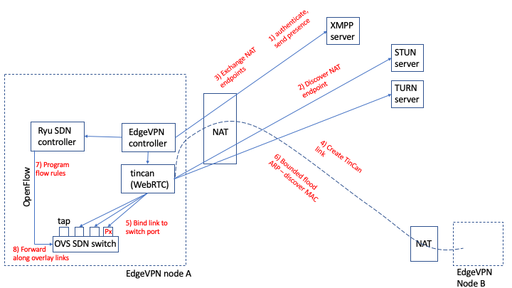
Now that we have gone through an overview, let’s revisit the figure above to highlight the overall sequence of steps in the lifetime of a node, with a high-level roadmap of which modules are responsible for the different steps:
-
Once a node starts, the first thing it does is authenticate with an XMPP server and send a presence message to other peers in the group to advertise itself. The XMPP server endpoint and credentials are taken from the configuration file, and the Signal controller module implements the XMPP client functionality
-
The node periodically queries STUN (and TURN, if configured) servers on the Internet to discover what public IP:port endpoint it might be reachable by other peers. This functionality is implemented as part of the WebRTC framework used by the tincan process
-
Now the node is able to begin creating tunnels. To this end, for each peer that is deemed a candidate for a link (i.e. a successor and/or a “long-distance” node in the Symphony ring), the node sends a connection request, with a list of its candidate endpoints (e.g. local, STUN, and TURN IP:port pairs) and certificate fingerprints via the XMPP server. The algorithm to select which links should be created to maintain a Symphony graph is implemented by the Topology controller module.
-
Once a candidate peer is selected, the process of actually creating an encrypted TinCan link is orchestrated by the LinkManager module in the controller. The LinkManager communicates with the tincan process through the controller API to initiate and query peer-to-peer link requests. These leverage WebRTC’s implementation.
-
Once a TinCan link is successfully created, it is bound to OVS switch ports on both ends of the link via a tap device. This is the first step needed to allow the switch to be able to forward messages along the link.
-
Focusing on TCP/IP applications, consider two nodes A and B, with respective MAC addresses MACa, MACb and IP addresses IPa and IPb. When a TCP/IP application in the node IPa wishes to communicate with IPb address, the first step it takes is to broadcast an ARP request - querying all nodes with a “who has IPb” message. This request is forwarded by the switch through multiple tunnels/ports, and then by other switches “downstream” along the ring, according to the bounded flood protocol outlined earlier. When node B matches the requested IPb, it sends an ARP reply, which is eventually received by node A through port Px of the OVS switch port, where Px is the port bound to the TinCan link from which the ARP reply was received. The ARP reply inclused the matching Ethernet MAC address MACb.
-
Upon receiving the ARP reply for IPb, the SDN controller in node A programs a flow rule in OVS that specifies that Ethernet frames with source address MACa and destination address MACb should be forwarded to port Px.
-
Now, further messages sent by A with source MACa and destination MACb will be forwarded along port Px by the OVS switch, whenever they are injected to the virtual network. Note that, not shown in this diagram, every node along the ARP reply path from B to A also programs a flow rule to forward source MACa to destination MACb (and vice-versa) through the port from which the reply was received, thus creating a path along the network for future communication between the two peers. Other paths are discovered for other nodes, following the same principle.